What Is a Tool Changer and What Types Are Available?

A tool changer is the quiet mechanism behind many modern CNC machining operations. It stores cutting tools, selects the required tool, and places it into the spindle with controlled precision. During a production cycle, this movement may happen dozens or hundreds of times. A short pause can determine whether a part meets its cycle-time target.

Dr. Scott Smith, a respected CNC machining educator and author, offers a useful principle: “A tool changer must support the process, not merely increase tool capacity.” That idea deserves attention. A larger magazine is not automatically better. A compact vertical machining center may need a reliable carousel, while a complex horizontal machine may require a chain-style magazine with many stations. Some systems also use robotic arms, twin grippers, or flexible tool storage.

The right tool changer depends on spindle design, tool size, change speed, chip control, and maintenance access. It must also match the machine’s software and safety controls. A poorly matched system can create vibration, tool collisions, or unnecessary downtime. Small details matter. Watch the gripper. Check the taper. Listen for unusual noise.

This guide examines the main types of tool changer available today, including automatic tool changers, manual systems, carousel models, drum magazines, and robotic solutions. It compares their working principles, strengths, limitations, and typical applications. The discussion will not treat automation as a perfect answer. Real workshops face worn tools, inconsistent operators, tight budgets, and imperfect maintenance records. Those realities should shape the decision.
What Is a Tool Changer and What Types Are Available?

What Is a Tool Changer and How Does It Work?

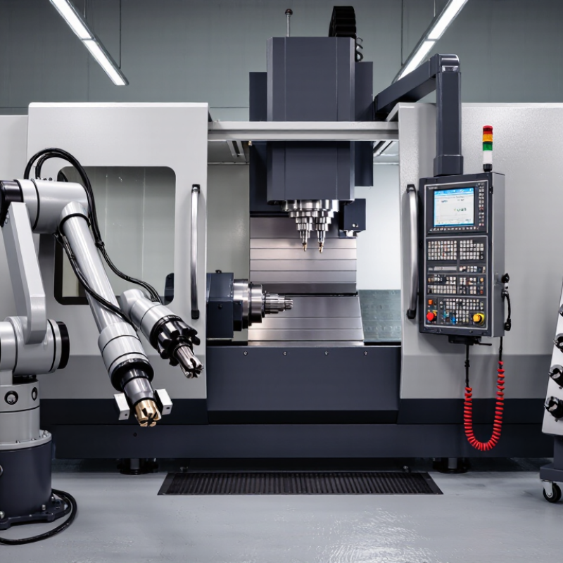
A tool changer is a machine system that replaces cutting tools during production. It removes the operator from repeated manual changes and keeps machining cycles consistent. When a program calls for another tool, the spindle stops at a precise position. The controller then commands the tool release, magazine movement, and tool pickup. A carousel, chain, or drum magazine stores the tools. Some machines use a separate transfer arm for faster exchanges.

The process depends on accurate positioning. Sensors check whether the tool is clamped, released, and correctly seated. If one signal fails, the machine should stop before cutting begins. This protects the spindle, workpiece, and operator. Tool changers differ in capacity and speed. Carousel types suit compact setups. Chain systems hold more tools for varied production. Robotic changers can support larger tools, but they usually require careful setup and maintenance.

Tips: Keep holders clean and dry. Even a small chip can create runout. Record each tool’s location after loading. Check clamp force and sensor readings during scheduled maintenance. In practice, no setup is perfect. A forgotten tool offset can spoil an otherwise accurate part. I have found that a short test cycle often reveals problems earlier than visual inspection. Take time to verify the first change.

Main Components and Operating Principles of Tool Changers

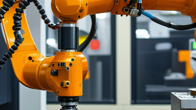
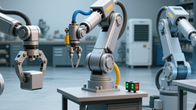
A tool changer connects one robot wrist to several end-effectors. Its main parts are straightforward. The robot-side master plate carries the locking actuator, locating features, and utility couplings. Each tool-side plate stores an end-effector, such as a gripper, welding head, or inspection probe. Precision pins guide alignment. A spring or pneumatic lock secures the interface, while sensors confirm locked and unlocked states. Electrical contacts and air, vacuum, coolant, or data couplers pass through matched ports. Good design separates guidance from clamping.

During a change, the robot approaches a rack at a controlled speed. It releases the current tool, backs away, and selects another plate. The actuator then closes locking jaws or engages a ball mechanism. Sensors should verify position, pressure, and tool identity before motion resumes. The International Federation of Robotics reported 541,302 industrial robot installations worldwide in 2023. That scale increases demand for repeatable interfaces. However, robot growth does not prove every changer is reliable.

Mechanical changers suit simple, rugged applications. Pneumatic versions offer fast locking and useful force, but they need clean, stable air. Electric changers simplify diagnostics, yet they can add heat, wiring, and software dependencies. Automatic multi-connection systems handle power, signals, and fluids together. A 2024 A3 industry report recorded 31,159 robot orders in North America during 2023. That figure shows the continuing scale of automation. In field work, I would inspect pins, wipe mating faces, and test the lock under simulated load. One overlooked chip can create false seating. No layout is perfect.

Common Types of Tool Changers and Their Features

A tool changer lets one machine switch end-effectors without a long manual stoppage. Common designs include manual, automatic, robotic, rotary, pneumatic, and hydraulic changers. Manual couplers suit low-volume work and simple fixtures. Automatic systems use locking mechanisms, sensors, and docking stations for repeated production. Robotic changers add electrical, pneumatic, or data connections, allowing one robot to handle gripping, welding, inspection, or fastening tasks.

Features determine practical value. Payload rating must cover the tool, workpiece, and acceleration forces. Repeatability matters when a gripper returns to the same position after every change. Some couplers use tapered locating pins, while others rely on mechanical balls or wedge locks. Pneumatic models often provide fast engagement, but air quality and pressure stability require attention. Electric versions can carry power and signals, yet their contacts need protection from dust and vibration. Rotary changers save floor space.

The International Federation of Robotics reported 541,302 industrial robots installed worldwide in 2023, a 10% annual increase. This expansion increases demand for flexible tooling. The Association for Advancing Automation also identifies end-of-arm tooling as a key factor in robotic application design. However, the fastest changer is not always the best choice. A poorly aligned docking station can create tiny errors, damaged connectors, and repeated downtime. Real production tests should measure cycle time, locking force, contamination resistance, and maintenance frequency. Data sheets help. They do not replace observation.

How to Choose a Tool Changer for Different Applications

Choosing a tool changer starts with the application, not the machine’s advertised speed. A milling center may need rapid automatic changes, while a robotic cell may require a lighter, simpler unit. Check tool weight, dimensions, gripping force, and available space around the spindle. Small details matter.

My first selection was too optimistic. I focused on change time and overlooked chip contamination near the coupling. In daily production, that caused inconsistent seating and extra cleaning. For dusty machining, choose sealed interfaces and inspectable contact surfaces. For high-speed work, confirm balance, repeatability, and locking stability at the actual operating speed.

Match the changer to the working environment. A heavy-duty model suits large cutting tools and frequent load cycles. A compact pneumatic changer may fit limited robot space, but its air quality and pressure must remain stable. For welding or assembly tools, electrical signals, hose routing, and safe release control deserve equal attention. Measure the complete tool package, including cables, coolant lines, and adapters. Do not rely only on catalog capacity.

Ask how maintenance will happen during a real shift. Can operators clean the coupling without removing major guards? Are wear indicators visible? Will replacement parts remain available for years? Testing one changer with representative tools is more reliable than comparing specifications alone. There is no perfect choice. Application data can still be incomplete.

Typical Tool Capacity Ranges by Tool Changer Type

Umbrella and carousel tool changers are commonly used for compact machining centers with low to medium tool requirements. Chain systems support larger tool inventories and are suitable for complex production. Matrix systems provide the highest storage flexibility for high-mix manufacturing and large tools. The ranges show common industrial configurations; actual capacity depends on machine design, tool size, weight, and available space.

Benefits, Limitations, and Maintenance Considerations

A tool changer automatically swaps cutting tools in a machine’s spindle. It reduces manual handling and keeps production moving between operations. A properly configured system can shorten cycle times and improve repeatability. It also lowers operator exposure to sharp edges, hot chips, and cutting fluid. The gains are not automatic, however. A changer may slow production when tools are poorly arranged or frequently misidentified. Tool changes also add mechanical complexity. One faulty sensor can interrupt an otherwise healthy machining cycle.

Maintenance requires disciplined, visible routines. Operators should inspect grippers, retention knobs, pockets, and drawbar surfaces for wear. Chips can prevent full seating, causing runout, vibration, or tool release. Clean contact surfaces with approved methods, not improvised abrasives. Check pneumatic pressure, lubrication, sensor signals, and clamp force at scheduled intervals. Record unusual noises and gradual positioning errors. Small changes often appear before a failure.

The machine environment matters. Heavy coolant mist can contaminate moving parts, while long tools may stress pockets during rapid motion. A practical maintenance log should include tool counts, alarm codes, inspection dates, and replaced components. Technicians should verify tool length data after service, even when the changer appears normal. That step is easy to skip. It should not be. The assumption that automation always improves output deserves skepticism. A simpler manual setup may suit short runs, limited tool variety, or infrequent production. Careful measurement remains more reliable than confidence.

What Is a Tool Changer and What Types Are Available? - Benefits, Limitations, and Maintenance Considerations

Tool Changer Type Primary Actuation Typical Tool Capacity Key Benefits Main Limitations Maintenance Considerations Suitable Applications
Manual Tool Changer Operator-operated mechanical locking mechanism One tool at a time; additional tools are stored separately Low purchase cost, simple construction, easy troubleshooting, and no control-system integration required. Tool changes require operator involvement, which increases cycle time and may reduce process consistency. Inspect locking surfaces, clean mating interfaces, check clamping force, and lubricate moving parts according to the equipment manual. Low-volume machining, prototyping, maintenance work, and machines with infrequent tool changes.
Pneumatic Automatic Tool Changer Compressed air-operated piston or gripper One tool at a time; tools are normally held in a rack, carousel, or fixed station Fast operation, relatively simple automation, compact design, and good suitability for repetitive production. Requires clean and stable compressed air; air leakage, pressure variation, and contamination can affect reliability. Drain moisture from the air system, inspect filters and tubing, check seals for leakage, and verify operating pressure regularly. CNC routers, machining centers, robotic cells, and automated production lines with moderate tool loads.
Hydraulic Tool Changer Hydraulic cylinder or hydraulic clamping circuit One tool at a time; external storage is commonly used High clamping force, smooth actuation, and suitability for heavy-duty tooling or demanding industrial environments. Higher system complexity, potential fluid leakage, greater installation requirements, and more extensive maintenance than pneumatic systems. Check hydraulic fluid level and condition, inspect hoses and seals, remove trapped air when required, and monitor pressure stability. Heavy machining, large robotic tooling, metal forming, and applications requiring high gripping force.
Servo or Electric Tool Changer Electric motor, servo drive, gearbox, or motorized locking system One tool at a time; tool storage is usually separate Precise positioning, programmable motion, reduced dependence on plant air, and useful feedback for monitoring tool engagement. Higher initial cost, more electronic components, and possible sensitivity to overloads, wiring faults, or control errors. Inspect connectors and cables, check motor temperature and backlash, verify position sensors, and follow drive-system diagnostics. Precision automation, clean manufacturing areas, flexible robotic systems, and installations without compressed air.
Carousel or Magazine Automatic Tool Changer Machine-controlled pneumatic, hydraulic, or electric mechanism Commonly several tools to several dozen tools, depending on machine design Enables unattended machining, organizes multiple tools, reduces operator intervention, and supports complex machining sequences. Requires more floor space and control integration; incorrect tool positioning or magazine indexing can interrupt production. Keep pockets and grippers clean, inspect indexing components, verify tool-presence sensors, check alignment, and remove chips from the change area. CNC machining centers, production milling, drilling, tapping, and multi-operation manufacturing.
Robotic Automatic Tool Changer Mechanical coupling with pneumatic, hydraulic, or electric locking One end effector or tool at a time; multiple tools can be stored in a dock or rack Provides flexible tool changes, supports multiple operations, and allows one robot to perform tasks using different end effectors. Requires accurate robot programming and mounting alignment; payload, torque, and cable-management limits must be respected. Inspect locking pins, guide surfaces, electrical contacts, air ports, and communication interfaces; verify repeatability and coupling security. Welding, assembly, material handling, deburring, grinding, dispensing, inspection, and flexible manufacturing cells.
Quick-Change Adapter System Manual or automated mechanical coupling, often with integrated utility connections One attached tool at a time; several adapters may be stored nearby Shortens changeover time, standardizes tool interfaces, and can combine mechanical, electrical, pneumatic, or fluid connections. Additional interface components add cost and stack-up length; contamination or wear can reduce coupling accuracy. Clean contact faces, inspect locating pins and locking elements, protect utility connectors, and check for wear or loss of repeatability. Robotic end-of-arm tooling, modular fixtures, packaging systems, and applications requiring frequent tool interchange.
Selection guidance: Choose a tool changer based on tool mass, required gripping force, change frequency, positioning accuracy, available utilities, allowable payload, environmental conditions, and the level of automation required.

Login