What Is a Robot Tool Changer and How Does It Work?

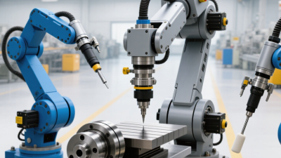
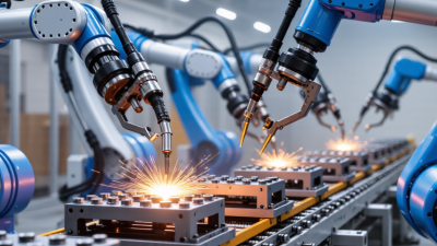
A robot tool changer is the mechanical and pneumatic interface that lets one robot use several end-of-arm tools. It can switch grippers, welding guns, screwdrivers, or inspection devices within seconds. The robot approaches a tool station, aligns its locking pins, engages the coupling, and confirms the connection through sensors. Utility passages then transfer air, electricity, data, or process fluids.

The market is gaining importance as factories seek flexible automation. The International Federation of Robotics reported 541,302 industrial robots installed worldwide in 2023, with more than 4.28 million robots operating globally. That installed base creates a significant need for reliable tool changing. Interact Analysis also identifies flexible automation and mixed-model production as major industrial robotics drivers. However, these reports rarely isolate robot tool changer revenue. That limitation matters. Market estimates can look more precise than the available evidence.

Robert Little, founder and former president of ATI Industrial Automation, described the design priority clearly: “The tool changer must be reliable, repeatable, and easy to maintain.” His point reflects shop-floor experience. A loose coupling can cause dropped parts, damaged connectors, or an interrupted production cell. A well-designed system feels almost invisible. The robot releases one tool, collects another, and returns to work with minimal delay. Still, speed alone is not enough. Payload, repeatability, safety monitoring, contamination control, and service access must be evaluated together. Engineers sometimes overlook maintenance space. That mistake can turn a compact installation into a frustrating repair task. This guide explains how a robot tool changer works, where it creates value, and which specifications deserve closer scrutiny.
What Is a Robot Tool Changer and How Does It Work?

What Is a Robot Tool Changer?

A robot tool changer is a mechanical interface between a robot arm and interchangeable equipment. It allows one robot to use several tools during a production cycle. Instead of stopping for manual replacement, the robot returns one tool and picks up another from a fixed storage station.

The system usually includes a robot-side unit, tool-side adapters, locking parts, and sensing elements. During a change, the robot moves to a docking position with controlled speed. A pneumatic or electric mechanism releases the current tool, then secures the replacement. Sensors confirm that the lock is fully engaged. This confirmation matters. A poorly seated tool can cause vibration, inaccurate motion, or equipment damage.

In practical installations, technicians check the locking surfaces, mounting bolts, air lines, and electrical contacts regularly. Dust, metal chips, and small alignment errors can prevent reliable coupling. The changer must also match the tool’s weight, center of gravity, torque, and required utilities. A heavy tool may fit mechanically but still exceed the robot’s safe payload. That mistake is easy to overlook. Tool changes also take time, so excessive switching can reduce productivity. Some systems provide air, power, data, or coolant through the connection, but every added passage creates another maintenance point. I would not treat sensor feedback as a substitute for inspection. Sensors can confirm position, yet they may not reveal gradual wear or contamination.

Why Industrial Robots Use Automatic Tool Changing

What Is a Robot Tool Changer and How Does It Work?

Industrial robots use automatic tool changing because one arm often performs several different jobs. A tool changer sits between the robot wrist and the end effector. It uses a mechanical lock, locating pins, and pneumatic or electrical connections. The robot releases one tool at a docking station, then locks onto another. Sensors confirm that the coupling is secure before production continues.

The need is growing. The International Federation of Robotics reported 541,302 industrial robots installed worldwide in 2023. Its World Robotics 2024 report also recorded about 4.28 million robots operating globally. More robots do not always mean more robot cells. Flexible tooling helps one cell handle drilling, gripping, dispensing, inspection, or finishing. This can reduce manual changeovers and keep valuable equipment productive.

Safety remains central. A reliable system checks tool presence, locking pressure, and signal continuity. Engineers should also review payload, torque, cable routing, and accidental release risks under ISO 10218 principles. In practical installations, a dirty docking plate can cause misalignment or a false sensor reading. Small details matter.

Automatic changing is not magic. It adds hardware, maintenance, and programming effort. The economics are not always obvious. A high-mix factory may recover that cost quickly, while a single-product line may gain little. Tool wear, calibration drift, and imperfect part positioning still require human oversight. That limitation deserves honest attention.

Key Components of a Robot Tool Changer

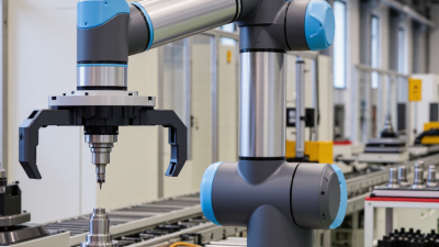
A robot tool changer connects one robot arm to several end-effectors, such as grippers, welders, or inspection probes. Its main components are a robot-side master plate and a tool-side plate. A locking mechanism joins them with repeatable mechanical force. Pneumatic, electrical, and fluid connections transfer air, power, signals, or coolant. Sensors confirm whether the coupling is locked and whether the correct tool is mounted.

The working cycle is simple but precise. The robot approaches a tool rack, aligns both plates, and activates the locking system. The controller checks sensor feedback before motion continues. The International Federation of Robotics reported 541,302 industrial robots installed worldwide in 2023. That growth increases the value of flexible tooling, especially where one robot must handle several operations. In factory commissioning, technicians often find that alignment errors create more downtime than the changer itself. Small errors grow.

Tips: Measure repeatability under real load, not only without a payload. Inspect locking surfaces, air seals, and connector pins regularly. Keep a record of tool weight, center of gravity, and connection cycles. The ISO 9283 framework is useful for evaluating robot performance, but it does not remove the need for application testing. I would not treat cycle time as the only KPI. A faster change is unhelpful if sensors deliver unreliable feedback. The overlooked detail is cable routing. A sharp bend can damage signals long before failure becomes visible.

What Is a Robot Tool Changer and How Does It Work? - Key Components of a Robot Tool Changer

Key Component Primary Function How It Works Typical Design Considerations
Robot-Side Plate Connects the tool changer to the robot wrist or mounting flange. The plate is fastened to the robot flange using a compatible bolt pattern. It remains attached while different tools are exchanged. Requires accurate alignment, sufficient rigidity, and compatibility with the robot's payload and wrist interface.
Tool-Side Plate Provides the mechanical interface for each end-of-arm tool. A separate tool-side plate is mounted to each gripper, welding gun, suction device, machining spindle, or other end effector. The robot-side plate locks onto it during a tool change. Should be lightweight but rigid, repeatable, and suitable for the tool's load, center of gravity, and operating environment.
Locking Mechanism Secures the robot-side and tool-side plates together during operation. A mechanical locking device, commonly operated by pneumatic pressure or another actuator, engages locating features and prevents the plates from separating. Many systems are designed to remain locked if actuation pressure is lost. Must provide high clamping force, resistance to vibration, controlled wear, and a reliable locked-state condition.
Locating Pins and Bushings Align the two plates and establish repeatable tool positioning. Tapered or precision locating elements guide the tool plate into the correct position before the locking mechanism clamps the connection. Alignment accuracy, contamination resistance, surface hardness, and ease of replacement are important for maintaining repeatability.
Pneumatic Passageways Transfer compressed air between the robot and the attached tool. Air ports on the two plates connect when the changer is locked, allowing the robot to operate pneumatic grippers, cylinders, clamps, or blow-off devices. Port size, pressure rating, sealing quality, flow requirements, and protection from debris must match the tool application.
Electrical Contacts Transfer power and control signals to the tool. Spring-loaded contacts or dedicated electrical connectors mate when the tool is coupled, enabling sensors, valves, motors, identification devices, or communication circuits to operate. Contact rating, pin count, mating cycles, shielding, insulation, and protection against dust or moisture should be evaluated.
Hydraulic or Fluid Ports Connect hydraulic circuits or other process-fluid lines when required. Self-sealing or flat-face couplings connect during tool engagement and disconnect when the tool is parked, limiting fluid leakage and contamination. Pressure, temperature, fluid compatibility, leakage control, and maintenance access are critical factors.
Tool Rack or Storage Station Stores tools safely when they are not attached to the robot. The robot moves to a defined station, releases the current tool, and engages another tool positioned in a known location. The station supports and protects each tool during storage. Must provide stable tool support, clear access, collision avoidance, drainage where needed, and repeatable docking locations.
Tool-Presence Sensor Confirms that a tool is correctly seated and retained. A proximity, limit, pressure, or position sensor verifies tool engagement. The robot controller can prevent motion if the expected tool state is not detected. Sensor placement should detect incomplete seating and tolerate vibration, dirt, and normal mechanical variation.
Lock-State Sensor Confirms whether the changer is locked or unlocked. The sensor monitors the position of the locking mechanism and sends status feedback to the robot controller or safety system before production motion begins. The feedback circuit should support fault detection and prevent operation when the lock state is uncertain.
Manual Release or Service Feature Allows authorized personnel to release or inspect the changer during setup and maintenance. A manual override, service port, or accessible release feature permits controlled tool removal when normal automated actuation is unavailable. Should be protected against accidental activation and used only under documented maintenance and safety procedures.
Seals and Protective Covers Protect internal mechanisms and connection points from contamination. Seals, covers, and guarded interfaces reduce the entry of dust, chips, moisture, weld spatter, or process fluids into moving and electrical parts. Protection level, chemical compatibility, temperature range, cleaning method, and replacement intervals should match the work cell.
Controller Interface Coordinates tool-change commands and verifies safe tool status. The robot program moves to the tool station, controls lock and unlock signals, checks sensor feedback, and resumes production only after the required conditions are confirmed. Interlocks, timeout detection, tool identification, fault recovery, and integration with cell safety controls are essential.

A robot tool changer is an interface that enables one robot to automatically exchange multiple end effectors. A typical change cycle consists of moving to the tool station, releasing the current tool, positioning the robot-side plate, locking onto the selected tool, connecting utilities, verifying sensor feedback, and returning to operation.

How a Robot Tool Changer Works Step by Step

A robot tool changer connects one robot arm with several end-effectors, such as grippers, welders, or suction tools. The process starts when the robot moves to a defined docking position. Sensors confirm alignment before mechanical locking begins. The changer’s master unit enters the tool-side coupling. Locking pins or a clamping mechanism then secure the attachment. Air, electrical, data, and fluid connections may engage at the same time. A signal confirms that the tool is fully seated. Without this confirmation, the robot should not continue.

The robot controller now loads the selected tool’s settings, including weight, center of gravity, and working coordinates. It moves slowly during the first verification cycle. A test signal checks the gripper or process head. Then production motion resumes. In a real cell, dust, cable wear, or slight misalignment can interrupt the sequence. That detail is easy to underestimate. Regular inspection matters. The International Federation of Robotics reported 541,302 industrial robot installations worldwide in 2023, with more than 4.28 million robots operating globally in its World Robotics 2024 report. As robot deployment grows, reliable tool exchange becomes increasingly important for flexible production. ISO 10218 guidance also emphasizes safeguarding, control systems, and risk assessment around industrial robots. Still, a tool changer is not automatically safe because it is automated. Engineers must validate locking, sensing, payload limits, and recovery procedures on the actual cell.

Common Types and Selection Factors

What Is a Robot Tool Changer and How Does It Work?

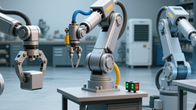
A robot tool changer lets one robot use several end-effectors during a production cycle. The robot moves to a storage station, releases one tool, and locks onto another. Mechanical locking pins provide repeatable positioning. Pneumatic, electrical, or fluid connections may transfer power and signals. A sensor confirms whether the tool is correctly attached. Without this confirmation, the robot should not continue.

Common types include automatic, manual, and hybrid tool changers. Automatic models suit frequent tool changes and high-volume production. Manual units are simpler and often fit smaller operations with limited changeovers. Hybrid designs combine automatic mechanical coupling with manual utility connections. Selection depends on payload, tool weight, operating speed, and available utilities. Repeatability is critical when the robot handles welding, gripping, drilling, or inspection tasks. Environmental factors matter too. Dust, heat, moisture, and vibration can shorten service life. In practical cell design, a changer rated only slightly above the real load may create avoidable risk. More capacity is not always better, because added mass can reduce robot speed and accuracy.

Tips: Check the complete load, including cables and workpieces. Confirm the robot flange pattern before ordering. Test locking sensors under real conditions. Keep spare seals and cleaning tools nearby. Fit matters. Not always. A carefully reviewed cycle-time study can reveal that a simpler changer meets the process better than a highly complex system.

Login