Why Choose Cluster Gears for Industrial Applications?
In industrial power transmission, Cluster Gears offer a practical way to manage high torque within limited equipment space. Their grouped gear arrangement can distribute loads across several contact points. This helps support steady power transfer in conveyors, mixers, machine tools, and heavy processing equipment. The design can also provide multiple speed ratios without requiring a larger gearbox. That matters where every millimeter affects installation and maintenance access.
Real performance depends on more than gear geometry. Engineers must check tooth strength, shaft deflection, bearing capacity, lubrication, and operating temperature. Alignment is critical. A small positioning error may create uneven loading, noise, or accelerated wear. Proper material selection and heat treatment also influence service life under shock loads. In practice, reliable results come from matching the gear cluster to the machine’s actual duty cycle, not simply choosing the highest rated model. That assumption can be costly.
Cluster Gears are not automatically the best solution for every application. They may require tighter manufacturing tolerances, careful assembly, and skilled inspection. Maintenance teams should monitor backlash, vibration, lubricant condition, and tooth contact patterns. These checks can reveal problems before an unexpected shutdown occurs. Designers should also consider efficiency, replacement access, and total ownership cost. A compact gearbox may save space but complicate repairs. The choice deserves a balanced review. When correctly specified and maintained, Cluster Gears can deliver durable, efficient, and flexible performance in demanding industrial environments. Yet field conditions often differ from design calculations, so testing and periodic reassessment remain essential.
Definition and Core Structure of Cluster Gears
Why Choose Cluster Gears for Industrial Applications?
Definition and Core Structure of Cluster Gears
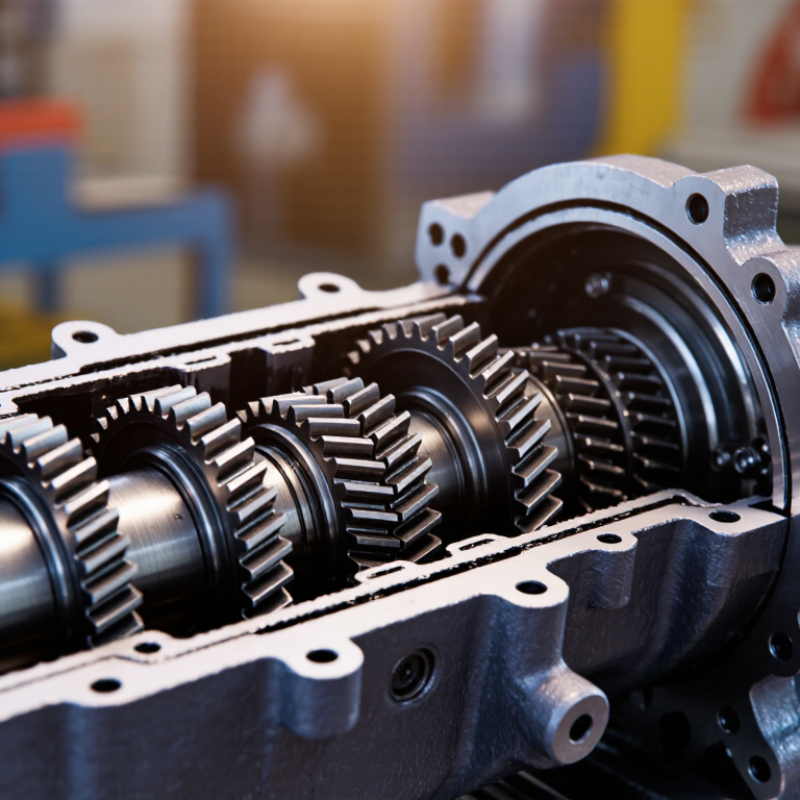
A cluster gear is an assembly of two or more gears mounted on one shaft. These gears rotate together as a unified mechanical group. Unlike a single gear, the cluster combines different tooth counts within a compact structure. This arrangement allows one transmission system to provide several speed and torque relationships.
The core structure usually includes a supporting shaft, multiple gear sections, keyways or splines, and accurately machined tooth profiles. Depending on the application, the gears may be permanently integrated or secured as separate components. During operation, one gear receives input power, while another transfers torque to the next shaft. The result is controlled power flow through a small installation space.
In industrial equipment, cluster gears are useful where high torque, repeated cycling, and limited space occur together. They appear in reduction units, material-handling systems, machine tools, and heavy-duty drive assemblies. Proper alignment is critical. Even a small shaft error can create uneven tooth contact, vibration, and premature wear. Maintenance teams often inspect tooth flanks for pitting, scoring, and abnormal polishing. These marks reveal real operating conditions better than a specification sheet.
No gear train is perfect.
A cluster design may improve efficiency, but it also increases manufacturing and inspection demands. Lubrication must reach every contact surface, including less accessible gear sections. Engineers should verify load distribution, bearing support, thermal expansion, and service access before selecting the arrangement. A compact structure can be powerful, yet difficult to repair. That practical trade-off deserves careful attention.
How Cluster Gears Transfer and Multiply Torque
Cluster gears help industrial gearboxes transfer torque through several meshing gears in a compact space. Their main advantage comes from gear ratio, not magic. A small driving gear turns a larger gear, reducing speed while increasing torque. The larger gear may share a shaft with another smaller gear. That second gear drives the next stage, multiplying the effect again.
This arrangement lets motors handle demanding loads, such as conveyors, mixers, hoists, and forming equipment. A multi-stage cluster can deliver high output torque without requiring an oversized motor. It also supports controlled speed reduction inside a relatively small housing. In practice, the calculation is clear, but the machine is not. Friction, tooth contact, shaft deflection, and lubrication reduce the final output.
Small errors matter. Poor alignment can concentrate force on one side of a tooth, causing noise, pitting, or premature failure. Engineers therefore check torque, service factors, bearing loads, and heat generation before selecting a gear set. Maintenance teams should inspect tooth patterns and oil condition, not only listen for unusual sounds. Load sharing may improve durability, but it is never automatic. Manufacturing tolerances and uneven stiffness can still overload one gear. Cluster gears remain highly effective when their ratios, materials, and operating conditions match the real machine. That last point deserves more attention than it often receives.
Why Choose Cluster Gears for Industrial Applications?
How cluster gears transfer and multiply torque through successive gear stages
This example assumes a constant 100 N·m input torque, a 1.5:1 reduction ratio per stage, and approximately 95% mechanical efficiency per stage. As additional stages engage, torque increases while rotational speed decreases, allowing cluster gears to support high-load industrial operations.
Industrial Applications That Benefit from Cluster Gears
Cluster gears are valuable where industrial equipment needs several speed ratios in a compact space. A cluster places multiple gears on one shaft, allowing controlled power transmission through different gear pairs. This design suits machine tools, automated production lines, material-handling equipment, and heavy-duty processing systems.
In machine tools, cluster gears help operators adjust spindle speed for cutting steel, aluminum, or composite parts. Each setting can match the tool diameter and cutting load more closely. That reduces heat, vibration, and unnecessary motor strain.
Conveyor systems also benefit when production speeds change between loading, processing, and packaging stations. In field inspections, technicians often notice smoother operation when gear engagement and lubrication are properly maintained. Small alignment errors matter.
Cluster gears can support industrial pumps, mixers, and compact drive assemblies where floor space is limited. Their shared shaft structure may reduce housing size and simplify power routing. However, the arrangement is not universally better. More gears can mean tighter manufacturing tolerances and more difficult inspection access. A damaged tooth may also affect several operating ratios. That risk deserves attention. Engineers should review torque cycles, shock loads, lubrication paths, and maintenance access before selecting this solution. In practice, a slightly larger gearbox can sometimes provide easier servicing and longer dependable operation.
Key Advantages Over Single-Gear Arrangements
Why Choose Cluster Gears for Industrial Applications?
Key Advantages Over Single-Gear Arrangements
In industrial machinery, a cluster gear uses several gears mounted or working together on one shaft. This arrangement can share torque, change speed ratios, and fit more power into a compact housing. A single gear pair often carries the entire load through two contact zones. That creates concentrated tooth pressure, especially during startup or sudden load changes. Cluster layouts distribute the work. Good design still matters.
During gearbox inspections, technicians often look for pitting, scoring, uneven wear, and loosened bearings. A properly aligned cluster can reduce tooth stress and support steadier operation under variable loads. It also offers more ratio options without adding a much larger transmission case. That flexibility helps conveyors, mixers, pumps, and machine tools meet different operating demands. Lower peak stress may reduce noise and heat. These gains are not automatic.
Each added gear introduces another mesh, bearing surface, and lubrication requirement. Poor timing, shaft deflection, or contaminated oil can cancel the expected advantage. Engineers should verify contact patterns, thermal behavior, fatigue life, and service access before selecting the arrangement. In practice, a cluster gear system rewards careful calculation and disciplined maintenance. It may be more efficient. It is not always simpler.
Factors for Selecting the Right Cluster Gear System
Why Choose Cluster Gears for Industrial Applications?
Selecting a cluster gear system starts with the load, not the catalog. A cluster gear shares torque across multiple meshing gears, which can reduce tooth loading and support compact transmission layouts. The International Energy Agency reports that electric motor systems consume roughly 53% of global electricity. This makes transmission efficiency a practical operating concern, not a minor specification.
Check torque, speed, duty cycle, shock loading, and available space. A gear system rated only for average torque may fail during startup or jam recovery. Field engineers should compare peak torque with calculated tooth and shaft stresses under ISO 6336 methods. The American Gear Manufacturers Association also recommends evaluating bending strength, surface durability, lubrication, and service factors. Small details matter.
Noise matters too.
For dusty plants, choose sealing and lubricant compatibility before chasing maximum power density. Helical cluster gears may reduce noise and distribute contact smoothly, but they can create additional axial forces. Bearings, housing stiffness, and alignment must therefore match the gear geometry. Thermal checks are essential in enclosed units, especially during continuous operation. The U.S. Department of Energy identifies proper sizing and maintenance as major factors in motor-system efficiency, yet gear losses still deserve measurement at the shaft. A practical acceptance test should record temperature, vibration, backlash, and output torque after stabilization. No selection is perfect. Engineers sometimes overvalue compactness and underestimate maintenance access, which can turn a clever design into an expensive interruption.

