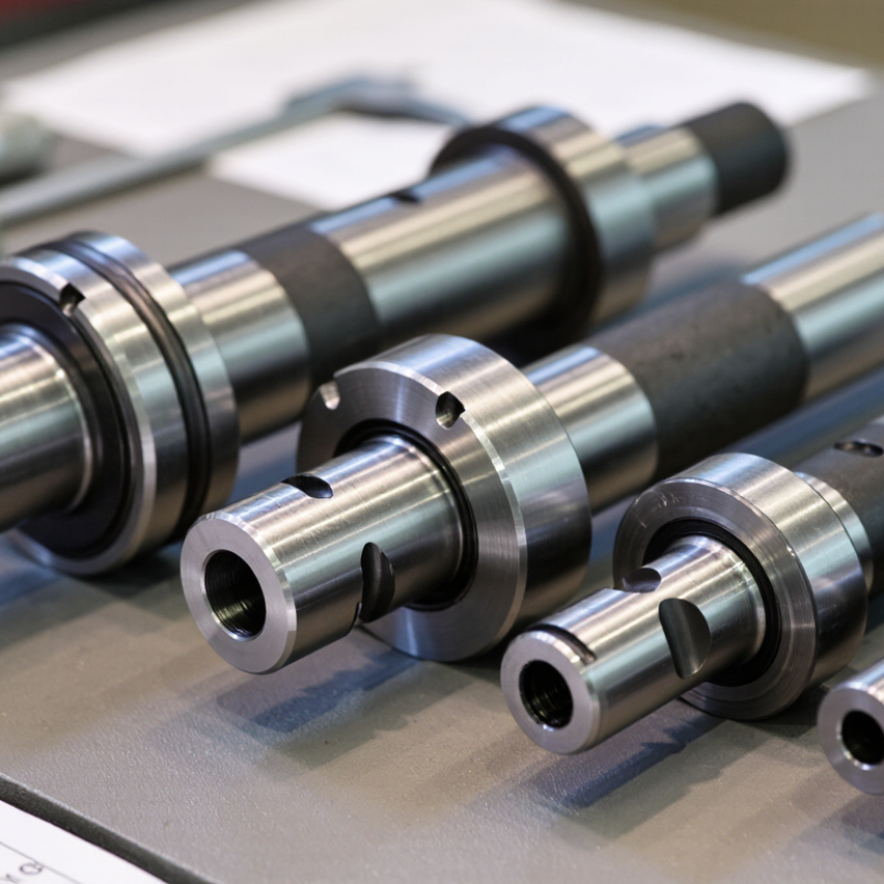
How to Choose the Right Carbon Steel Shaft?

Choosing the right Carbon Steel Shaft begins with the load, not the catalog photograph. A shaft may appear strong on paper, yet fail after repeated bending, poor alignment, or an undersized keyway. The 2024 World Steel Association report recorded approximately 1.89 billion tonnes of crude steel production in 2023. This scale reflects steel’s importance, but it does not make every grade suitable for rotating equipment.

The real selection process is more specific. Engineers should calculate torque, bending moment, speed, shock loading, and fatigue cycles. Diameter matters. So does surface condition. A small machining mark can become a stress concentrator under continuous rotation. ASTM A29/A29M provides general requirements for carbon and alloy steel bars, while ASTM A108 covers cold-finished carbon and alloy steel bars. These standards support material consistency, but they cannot replace application testing.

Start with the working environment. Low-carbon steel offers easier machining and welding. Medium-carbon grades can provide higher strength after heat treatment. Neither choice automatically solves corrosion, wear, or fatigue. That part is often underestimated.

A practical review should compare yield strength, tensile strength, hardness, machinability, and cost. It should also verify tolerances, straightness, keyway design, and bearing fits. The right answer may not be the strongest grade. Over-specifying steel can increase cost without improving service life.

There is no universal shaft grade. That is the uncomfortable truth. Before ordering, confirm the actual duty cycle, safety factor, and inspection requirements with a qualified materials or mechanical engineer. Good decisions come from measured conditions, reliable standards, and a willingness to question convenient assumptions.

How to Choose the Right Carbon Steel Shaft?

Define the Shaft’s Intended Load, Motion, and Operating Conditions

How to Choose the Right Carbon Steel Shaft?

Define the Shaft’s Intended Load, Motion, and Operating Conditions

Start with the shaft’s job, not its diameter. Define the intended load, motion, and operating conditions before comparing carbon steel grades. Will it carry a steady radial load, a reversing torque, or both? Write down peak loads, not only average values. Peak loads matter. An overlooked start-up shock can bend an otherwise adequate shaft. If gears, pulleys, or couplings attach to it, record their positions and distances. These details control bending and torsion.

Motion changes the selection. A slowly rotating shaft may tolerate different stresses than one running at 1,800 revolutions per minute. Repeated starts, stops, and direction changes can create fatigue cracks near keyways and shoulders. Check shaft speed, deflection limits, bearing locations, and required alignment. A calculation based only on static strength is incomplete. I have seen shafts pass a basic torque check yet fail after months of cyclic service.

Operating conditions also deserve specific attention. Moisture, dust, heat, vibration, and chemical exposure can reduce service life. Carbon steel may need heat treatment, surface protection, or a different material when corrosion is persistent. Measure the actual temperature around seals and bearings. Do not rely on room-temperature assumptions. I have learned that a clean spreadsheet can still hide a poor assumption. Leave room for manufacturing tolerances, installation errors, and unexpected impact loads. A careful review of the real machine often changes the original shaft design.

How to Choose the Right Carbon Steel Shaft

Define the shaft’s intended load, motion, and operating conditions before selecting a material grade.

Intended Load

Check torsion, bending, axial force, shock loading, and combined stresses. Use yield strength as a starting point and apply an appropriate safety factor.

Motion

Rotating shafts require fatigue analysis, balanced geometry, suitable surface finish, and attention to stress concentrations at keyways and shoulders.

Operating Conditions

Account for temperature, corrosion, lubrication, impact, wear, and manufacturing condition. Heat treatment and diameter can significantly change performance.

Representative room-temperature mechanical values for commonly specified carbon-steel conditions. Exact properties depend on heat treatment, section size, and applicable material standards.

Compare Carbon Steel Grades by Strength, Hardness, and Machinability

Choosing a carbon steel shaft starts with its working load, surface contact, and machining route. AISI/SAE 1018 offers moderate strength, about 440 MPa tensile strength in typical cold-drawn data. Its hardness often sits near 126 HB, according to ASTM A29/A29M reference ranges. It machines easily and suits light-duty shafts, pins, and spacers.

AISI/SAE 1045 provides a stronger middle option. Normalized material commonly reaches about 570–700 MPa tensile strength and 170–210 HB hardness. ASM International machining data places its machinability near 57% of free-cutting steel. That reduction matters. Tool wear becomes visible around keyways and shoulder transitions.

AISI/SAE 1095 can offer higher hardness after heat treatment, but machinability falls sharply. Industry data often rates it near 40–45% machinability, depending on condition.

Do not treat these figures as guarantees. They change with bar diameter, heat treatment, and supplier processing. A shaft tested at the surface may not represent its core. That detail is easy to miss. In practical selection, 1018 is forgiving, 1045 balances strength and cutting time, and 1095 demands tighter heat-treatment control. The SAE J403 chemical limits help verify grade identity, while ASTM tensile and hardness testing confirms the delivered condition. One overlooked issue remains: a harder shaft may resist wear but create more difficult drilling, turning, and repair work.

Select the Proper Shaft Diameter, Length, and Structural Design

How to Choose the Right Carbon Steel Shaft?

Select the Proper Shaft Diameter, Length, and Structural Design

Choosing a carbon steel shaft starts with real loads, not appearance. Calculate transmitted torque, bending force, shock loads, and rotational speed. Diameter must resist both twisting and bending. A shaft can survive static loading but fail under repeated cycles. Fatigue matters. I usually check the combined stress before selecting a final size. A quick calculation can look convincing, yet it may miss a keyway or sudden load change. I have made that mistake.

Length affects deflection, alignment, and vibration. Measure the distance between bearings, then include overhangs, couplings, and working clearances. A long shaft may need a larger diameter or an intermediate support. Keep unsupported spans short where possible. Check critical speed when rotation is high. Thermal expansion also deserves attention, especially in equipment with changing temperatures. Small errors become expensive later.

Structural design controls durability. Use generous fillets near shoulders to reduce stress concentration. Inspect keyways, splines, threads, and bearing seats carefully. These details often fail before the shaft body. Solid shafts suit many compact drives, while hollow designs can reduce weight when stiffness remains adequate. Choose strength and toughness based on the actual service environment, not only tensile strength. Consider corrosion, surface hardness, and machining tolerances. A qualified engineer should verify the calculations, drawings, and safety factors before production.

Evaluate Surface Finish, Corrosion Protection, and Heat Treatment

How to Choose the Right Carbon Steel Shaft?
Evaluate Surface Finish, Corrosion Protection, and Heat Treatment

A shaft can meet its diameter requirement and still fail in service. Surface finish affects friction, seal life, and fatigue performance. For bearing seats, specify a controlled roughness value, such as Ra, rather than requesting “smooth.” A ground surface may reduce wear, but grinding burns can weaken the surface. Inspect the shaft visually and measure critical areas with suitable instruments. Small grooves around a shoulder deserve attention.

Corrosion protection depends on the working environment. Indoor machinery may need only oil, proper packaging, and dry storage. Shafts exposed to moisture, chemicals, or coastal air need stronger protection. Options include plating, conversion coatings, controlled painting, or corrosion-resistant sleeves. Coating thickness must not change the fit. Salt-spray data can help, but it does not perfectly represent real service. I have learned that a shiny surface is not automatically a durable surface.

Heat treatment controls hardness, strength, and toughness. Through-hardening suits some uniform loads, while induction or case hardening can protect wear zones. Tempering is essential after hardening because excessive hardness may create brittle behavior. Ask for hardness results, treatment records, and batch traceability. Check both the surface and core when performance depends on depth. A supplier may provide impressive numbers, yet the test location can be overlooked. That detail deserves verification. When selecting a shaft, match the treatment depth to the actual contact load, not an assumed operating condition.

Verify Manufacturing Standards, Tolerances, and Supplier Quality

Choosing a carbon steel shaft begins with evidence, not a polished product photo. Ask which manufacturing standard governs the material, heat treatment, and surface finish. Common references include ASTM, ISO, or national standards, but the listed code must match your application. Request the material certificate and check its heat number, chemical composition, tensile strength, and hardness. Small details matter. A shaft may look precise while hiding inconsistent hardness.

Tolerances deserve practical attention. Confirm diameter, straightness, roundness, concentricity, and keyway dimensions on the drawing. Do not accept “high precision” without numerical limits. For a rotating shaft, even a few hundredths of a millimeter can affect bearings, vibration, and service life. Ask how measurements are taken, including gauge type, calibration date, and sampling frequency. A supplier who cannot explain the inspection process creates unnecessary risk. I once underestimated surface roughness in a tight-fit assembly; the drawing was correct, but the inspection discussion was too vague.

Supplier quality should be tested through records and repeatability. Review inspection reports, traceability procedures, nonconformance handling, and corrective-action examples. Visit the facility when production volume or safety makes consistency critical. Check whether inspectors measure finished shafts under controlled conditions, not beside a hot machine. Request a sample batch before approving regular production. Compare several pieces, not only the best-looking one. Clear communication matters too. If a supplier challenges an unrealistic tolerance, that can show engineering honesty rather than resistance. Still, verify every claim with documented results.

How to Choose the Right Carbon Steel Shaft? - Verify Manufacturing Standards, Tolerances, and Supplier Quality

Selection principle: Define the material grade, delivery condition, dimensional tolerance, surface finish, straightness, inspection method, and traceability requirements before comparing quotations.
Decision Dimension Typical Requirement or Reference Practical Selection Data How to Verify Purchasing Acceptance Note
Application load Consider bending, torsion, axial load, fatigue, shock, and bearing pressure. Use a design calculation with the shaft diameter, unsupported length, keyways, shoulders, operating speed, and safety factor. Review the engineering drawing and load calculation before selecting a grade. Do not select material by tensile strength alone; fatigue concentration at steps and keyways may control the design.
Common carbon steel grade ASTM A29/A29M and ASTM A108 cover general requirements and cold-finished carbon and alloy steel bars. EN 10083-2 covers specified quenched and tempered steels such as C45. AISI/SAE 1018 or 1020: economical, lower carbon, suitable for general-purpose shafts with moderate loading. AISI/SAE 1045 or C45: higher carbon and commonly selected when greater strength and wear resistance are required. Check the material certificate for grade, heat number, chemical composition, and delivery condition. Treat 1045 and C45 as comparable design options only after confirming the applicable standard and required chemistry; they are not automatically identical.
Chemical composition Must comply with the selected material standard and grade limits. For typical carbon grades, carbon content increases from approximately 0.18–0.23% in 1018 to approximately 0.42–0.50% in 1045; exact limits depend on the selected standard. Review a heat-specific test certificate and, when risk justifies it, perform positive material identification using suitable analytical equipment. Reject certificates that show only a generic grade name without heat number, standard designation, or measured chemistry.
Delivery condition Cold drawn, cold finished, normalized, or quenched and tempered conditions provide different strength, hardness, and machinability. Choose cold-finished material for improved dimensional consistency; choose normalized or quenched-and-tempered material when mechanical properties are specified by design. Confirm the delivery condition on the certificate and compare hardness or tensile results with the purchase specification. Do not mix hot-rolled, cold-finished, normalized, and quenched-and-tempered data when comparing quotations.
Dimensional tolerance ISO 286-1 and ISO 286-2 define limits and fits, including shaft tolerance positions such as h6 and h7. Example for a 30–50 mm shaft: h6 is 0 to −16 µm; h7 is 0 to −25 µm. The permissible deviation changes with the nominal diameter range. Measure with calibrated micrometers or a suitable gauge at several angular positions and along the functional length. State the nominal diameter, tolerance class, fit, measurement temperature, and measurement locations on the drawing.
Fit selection Use an ISO 286 hole-basis or shaft-basis fit according to the bearing, bushing, gear, or coupling function. A shaft tolerance such as h6 or h7 may be appropriate for controlled fits, but the final fit also depends on the mating bore tolerance, temperature, lubrication, and assembly method. Verify both shaft and mating-part tolerances rather than checking the shaft in isolation. Avoid vague terms such as “precision diameter” without a numerical tolerance and specified fit.
Surface roughness Specify the required surface texture on the drawing; ISO 21920-1 is used for profile surface-texture indication. Typical engineering targets are Ra 1.6 µm for a well-finished turned surface and Ra 0.8 µm or lower for a precision-ground bearing journal, subject to the application. Use a calibrated contact or optical surface-roughness instrument with the correct cutoff and evaluation length. Surface roughness is not a substitute for diameter, roundness, cylindricity, or runout control.
Straightness and runout Specify geometric tolerances according to the functional length and rotational requirements. For a general purchasing target, a straightness or total indicated runout limit such as 0.05 mm per 300 mm may be used only when supported by the design; precision rotating assemblies may require tighter limits. Check on calibrated V-blocks, centers, or a suitable inspection fixture using a dial indicator or equivalent system. Define datum locations, inspection length, support method, and whether the requirement is straightness, concentricity, or total runout.
Mechanical properties ISO 6892-1 provides a tensile-testing method for metallic materials; specified values depend on grade and condition. Require yield strength, tensile strength, elongation, and hardness only when they are relevant to the design and clearly linked to the delivery condition. Review heat-specific test results and the test method, specimen orientation, and condition stated on the report. Mechanical-property values from one condition must not be used to approve material supplied in another condition.
Hardness ISO 6508-1 covers Rockwell hardness testing; other hardness methods may be specified by the material standard. Set a hardness range only when needed for wear, machinability, heat treatment, or process control. Hardness alone does not prove chemical compliance. Use a calibrated tester, an appropriate scale, and a defined test location away from edges and damaged surfaces. Require conversion tables or equivalent reporting rules when comparing different hardness scales.
Inspection sampling ISO 2859-1 provides attribute-sampling procedures using acceptance quality limits. Define lot size, inspection level, AQL, critical/major/minor defect classification, and whether 100% inspection is required. Review the supplier inspection plan and the final inspection report for actual sample size and results. Sampling plans reduce inspection effort but do not eliminate the need to control critical characteristics.
Calibration and measurement system Inspection equipment should be calibrated and traceable to recognized national or international measurement standards. For tight fits, use equipment whose resolution and uncertainty are suitable for the specified tolerance; a 0.01 mm instrument may be inadequate for a 0.016 mm tolerance. Check calibration certificates, equipment identification, calibration status, and measurement uncertainty. Request a measurement-system study when dimensional variation is close to the acceptance limits.
Supplier quality system ISO 9001 certification can indicate a documented quality-management system, but it does not by itself guarantee product conformity. Prefer suppliers able to provide process controls, inspection records, nonconformance handling, corrective actions, and change notification. Review the certificate scope and validity, quality procedures, sample reports, and previous nonconformance records. Evaluate actual process capability and inspection evidence in addition to certification status.
Traceability Material and finished shafts should remain traceable to the heat, lot, production route, and inspection records. Require permanent or controlled identification linking each production lot to the material certificate and final inspection report. Match the product marking, packing list, certificate, and inspection report by heat or lot number. Do not accept mixed lots unless each lot is separately identified and documented.
Corrosion protection and packaging Carbon steel requires protection against moisture and contamination during storage and transport. Specify temporary rust preventive, end protection, separators, wrapping, storage conditions, and allowable surface condition at receipt. Inspect journals, threads, keyways, and ends for corrosion, dents, burrs, and handling damage. Clarify whether light removable discoloration is acceptable and whether corrosion on functional surfaces is rejectable.
Recommended purchase specification: Include shaft diameter and length, material grade and standard, delivery condition, heat-treatment requirement, fit and tolerance class, surface roughness, straightness or runout, mechanical properties, inspection plan, certificate requirements, traceability, packaging, and change-control requirements.

Login